Thursday, January 31, 2008

CPU Sockets


A CPU socket or CPU slot is a connector on a computer's motherboard that accepts a CPU and forms an electrical interface with it. As of 2007, most desktop and server computers, particularly those based on the Intel x86 architecture, include socketed processors.

Most CPU-sockets interfaces are based on the pin grid array (PGA) architecture, in which short, stiff pins on the underside of the processor package mate with holes in the socket. To minimize the risk of bent pins, zero insertion force (ZIF) sockets allow the processor to be inserted without any resistance, then grip the pins firmly to ensure a reliable contact after a lever is flipped.

As of 2007, several current and upcoming socket designs use land grid array (LGA) technology instead. In this design, it is the socket which contains pins. The pins contact pads or lands on the bottom of the processor package.

In the late 1990s, many x86 processors fit into slots, rather than sockets. CPU slots are single-edged connectors similar to expansion slots, into which a PCB holding a processor is inserted. Slotted CPU packages offered two advantages: L2 cache memory could be upgraded by installing an additional chip onto the processor PCB, and processor insertion and removal was often easier. However, slotted packages require longer traces between the CPU and chipset, and therefore became unsuitable as clock speeds passed 500 MHz. Slots were abandoned with the introduction of AMD's Socket A and Intel's Socket 370.
Assignment


Step 1
Before you start: Ground yourself. Lightly touch your PC's metal chassis to discharge any current from your body. Then unplug the power cable.
What you'll need: A phillips-head screwdriver, needlenose pliers, and antistatic wrist strap.


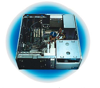
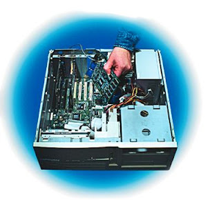
Turn off the computer and open the case. Locate an available PCI slot for the MPEG-2 decoder card (if your kit includes one). If you're installing a SCSI drive and you don't yet have a SCSI controller in the system, you'll need a second slot for the SCSI card.


Step 2
Remove the end bracket for the selected slot, insert the card, and secure the card's own end bracket.


Step 3
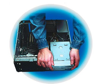
Locate an available 5.25-inch drive bay that opens onto the front of the case. Remove the bay cover if necessary.


Step 4
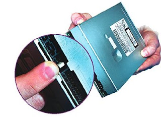
Configure the jumpers on your DVD drive. For an IDE drive, set the jumpers for either master, slave, or sole drive, depending on what else is on the channel. For a SCSI drive, set the jumpers to the correct ID or termination setting.


Step 5
Secure the drive in the bay.


Step 6
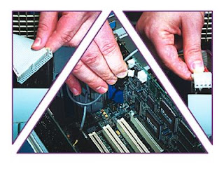
Attach the cables. Connect the DVD drive to the IDE or SCSI bus and to the power supply. Also connect the DVD drive to your sound card - or connect the decoder card (if included) to the DVD drive and sound card. (If you already have a CD-ROM drive, you can use a micro stereo patch cord to connect the external headphone jack on the DVD drive to your sound card's line-in jack).


Step 7
Close the case, turn on the power, and install any necessary drivers or software.

Install DVD drive

Install DVD drive: "Step 1
Before you start: Ground yourself. Lightly touch your PC's metal chassis to discharge any current from your body. Then unplug the power cable.
What you'll need: A phillips-head screwdriver, needlenose pliers, and antistatic wrist strap.
Turn off the computer and open the case. Locate an available PCI slot for the MPEG-2 decoder card (if your kit includes one). If you're installing a SCSI drive and you don't yet have a SCSI controller in the system, you'll need a second slot for the SCSI card."